Fri Dec 14 '18 Announcement
over 7 years ago
– Fri, Dec 14, 2018 at 07:51:08 AM
Hello dear backers,
As promised, we will start giving you updates on the manufacturing developments of your Raise keyboard every two weeks.
The tooling process has been going smoothly.
It’s only been around 4 weeks since we’ve started so there are only a few small things that have been created and tested.
Here’s our die cut machine for the Mylar bottom plate! Exciting!?
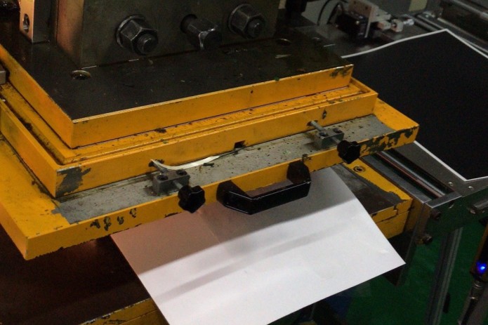
Die cut machine
We’ve received photos of the samples of the silver Mylar sticker that will be placed at the bottom of your keyboard. They will have the exact color and texture as the aluminum body.
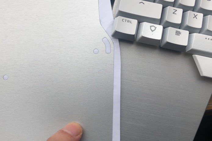
Silver Mylar
We also have photos of the rubber feet of both the black and silver version. Each half of the keyboard will have 6 rubber feet, all with a height of 1 millimeter.
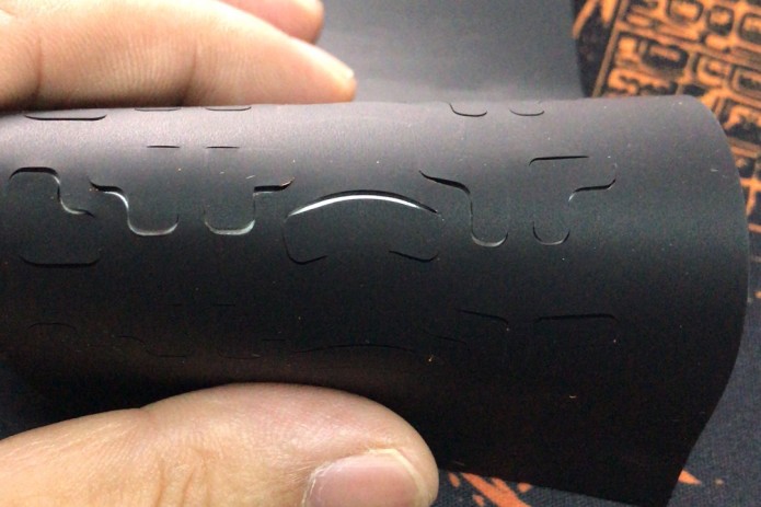
Black rubber feet
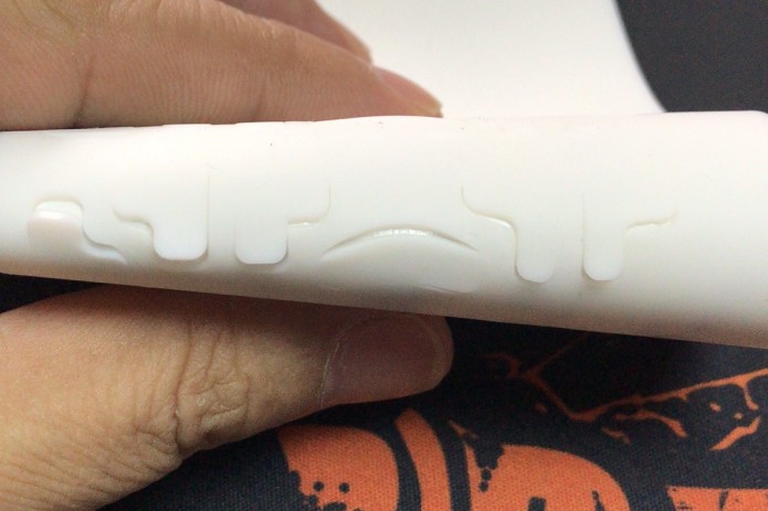
White rubber feet
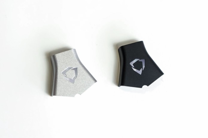
One component we have that didn’t require a tooling is the white keycap/switch puller. We still need to modify the logo on it but that's just a minor adjustment.
Everyone who ordered a Raise will get one: black for the black Raise, and white for the silver Raise.
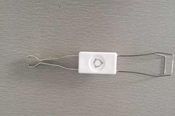
Keycap-switch puller
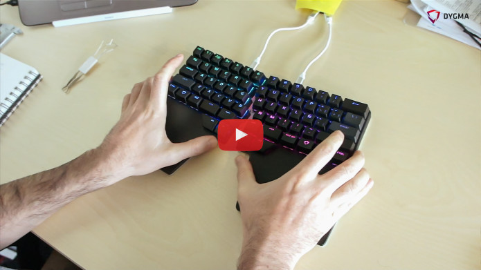
We are hoping to receive more photos in the next 2 weeks. The next component that we’re expecting is the palm pads! We talked about the new palm pad solution in one of our last updates. Give it a quick read or watch the video we made to learn more about it.
That’s all for the manufacturing updates!
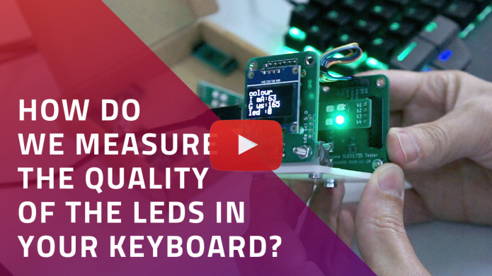
As for the technical updates, we have been working on measuring the quality of the LEDs.
We noticed that the intensity of green color in the LEDs was not the same as the previous samples. Initially, we thought it was because of the transparent base. But then we quickly realized that the color itself was different.
It was hard to spot early on because we found out that Matt, our CTO, and Manel, our Product Manager, are actually color blind ?
But good thing Luis, our all-knowing CEO, was able to spot it!
In order to check this, we made a test jig to compare their intensities and had the results in a graph. The result we want is for each color, -red, green, blue-, to have the minimum of the other 2 colors.
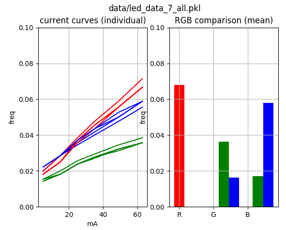
Graph of the color distribution that we want
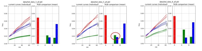
What we learned was that for the latest batch of LEDs, the green LED had far too much blue, so that’s why it didn’t look as green as it should.
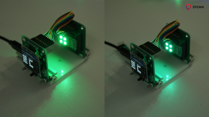
The test jig for the LEDs
The left LEDs look greener than the right one. The left one is what we want!
So we had to recheck all the LED samples we had ever received from our supplier and checked them all ourselves. We then cross-referenced them to the pack of LEDs it came from and sent our data back to our suppliers.
If we’re going to mass produce the Dygma Raise, we need to make sure we are using the right LEDs, even if it means doing the extra quality control check ourselves.
In the next week, the test jig will be doing a 24-hour burn test on all of the LEDs. This will allow us to check how things change over time so we can make sure that the quality of the LEDs is the best we can achieve.
We’ll be keeping you updated on our developments, as always. But if you have any ideas on how we can improve our updates, please let us know!
Thanks for reading our update!
- Dygma Team
____________
Like us on Facebook
Follow us on Twitter
Follow us on Instagram
Subscribe to our Youtube
Fri Nov 30 '18 Announcement
over 7 years ago
– Fri, Nov 30, 2018 at 01:12:29 AM
Hey there backers!
We've started manufacturing. Yey! ?
This is a milestone for us!
Other good news is that we passed our last pre-test for our PCBs. Yey! ?
If you remember in our previous update, we said that we did 3 tests. We passed 2 and failed 1. We worked with a consultant in the UK to help us fix the issue.
This was the last compliance pretest, the electrostatic discharge test (ESD), and we passed!
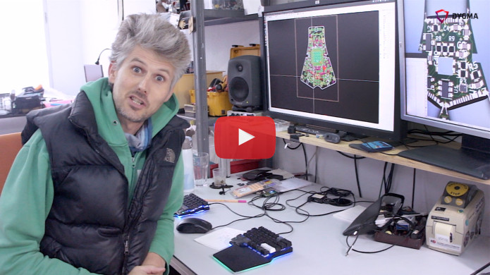
Matt explains all about it in the video below:
We can comfortably say that things are going smoothly so far. The tooling components are all being made and fingers crossed we get to test them right on schedule.
Every 2 weeks we will be posting updates with images and videos so stay tuned!
If there’s anything you’d like to learn more from us or the development, just write it down in the comments below!
Thanks guys!
- Dygma Team
____________
Like us on Facebook
Follow us on Twitter
Follow us on Instagram
Subscribe to our Youtube
Fri Nov 16 '18 Announcement
over 7 years ago
– Fri, Nov 16, 2018 at 05:43:41 AM
Hi guys!
How’s everyone doing?
We are quickly moving forward with the developments here at Dygma. It’s been non-stop!
In this update, we will be talking about our perfect solution of the joint of the Raise. We will also explain how we found a cool solution for our palm pads!
Of course, we also have something special for our tech fans out there! Apart from our development updates, we also have a video of Matt explaining the cause and effect of switch bouncing.
Happy reading!
The perfect joint for our split keyboard
The joint of the keyboard has been something that we’ve been working on since the beginning of the project.
If you remember, we did an update called the “Evolution of the Joint” and did multiple experiments that you can read all about here.
Now we have a clear working sample of the joint. It is as resistant as we want it.
Our current challenge is how to translate this into mass production. So we have created a very accurate joint sample that the factory will use as a reference for production.
The perfect split keyboard joint
We have added enough magnets and adjusted the tolerances of the metal pins to have the feeling we want for the joint. With stronger magnets, it is much easier to attach. You can even hear a "clack" sound when it attaches. You can hold it with one hand and it feels like it's one solid piece. But it's also very easy to detach.
After all those experiments, we have finally reached the solution that we've been looking for! We have the perfect joint!
A cool solution for our palm pads
Our solution for our palm pads
A LITTLE RECAP
We already had a solution for the palm pads. We had our supplier and we already specified what we wanted. The palm pad we wanted looked something similar to the image below but with our palm pad shape.
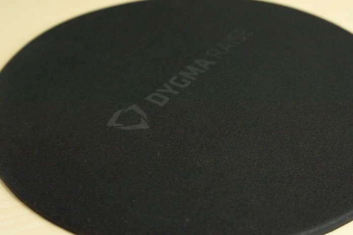
Initial palm pad sample
It would have had a PU anti-slip material at the bottom, PU inside, cloth on the top, and a soft curve around the edges.
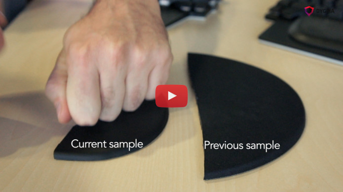
We were concerned with the softness of the palm pads. We want the palm pads to be soft, but not too soft. So we needed to find the right balance. Our supplier ensured us in our previous visits that they can find this balance.
Unfortunately, during our last visit to Shenzhen, the sample that the manufacturer showed us was too hard.
ADDING SILICONE
So we started working with a different material inside the palm pad. We decided to add silicone.
But the samples that the manufacturer showed us were still not what we wanted.
This sample was too soft.
This was too thick. And they couldn’t make it any thinner.
The thickness requirement we have for our palm pads is 7.5mm.
SEARCHING THE MARKET
It was a frustrating time for us as we were already set to have the tooling made for the other components. We tried to look for a reference in the market but we didn’t find anything that was similar to what we wanted with the same materials.
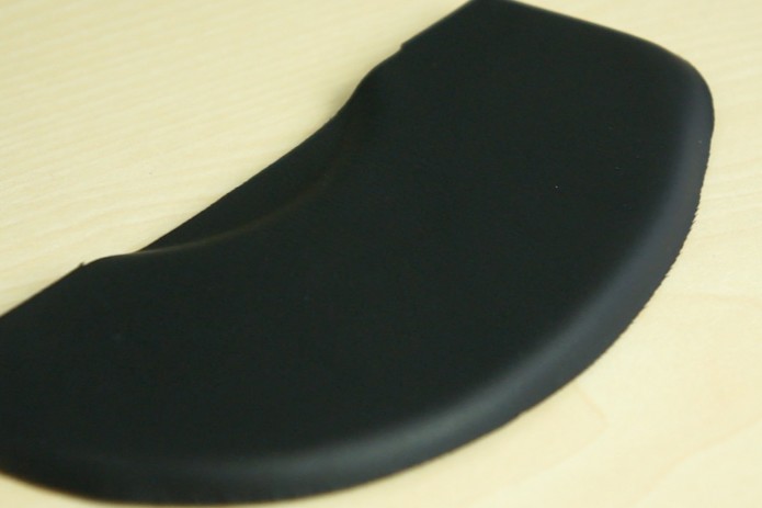
Then we found something slightly similar to what we wanted. The difference was that it had a PU skin instead of cloth.
The PU skin is similar to synthetic leather. It's also easy to clean.
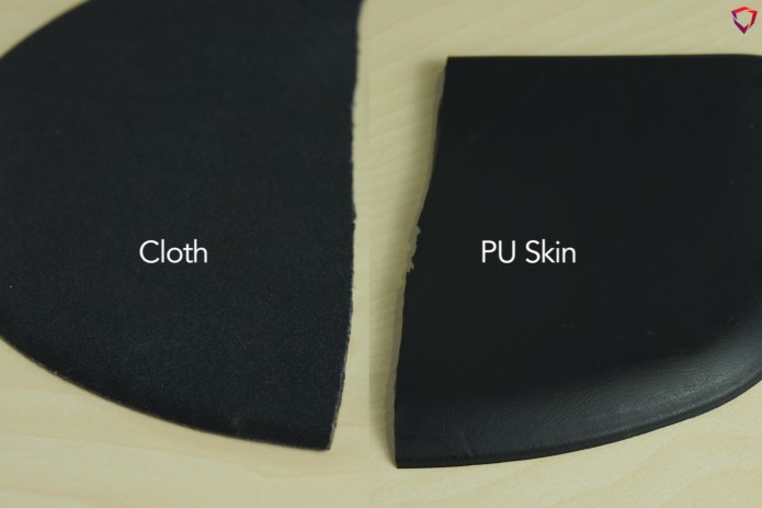
PU skin instead of cloth
This palm pad had silicon inside, PU, anti-slip PU, and PU skin. We decided that this would be a better solution.
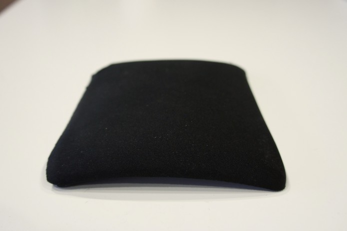
So we started looking for a different supplier and then we finally found this!
New palm pad sample
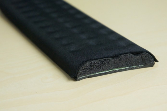
It will have a layer of EVA underneath the PU skin to make it softer. Then a layer of silicon, and an adhesive material at the bottom.
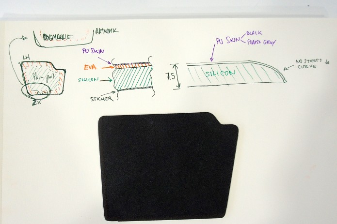
Materials inside the palm pad
We really like the adhesive material at the bottom.
The anti-slip material of the previous sample was great, but if you would pick up your keyboard, for example, the palm pad would fall off.
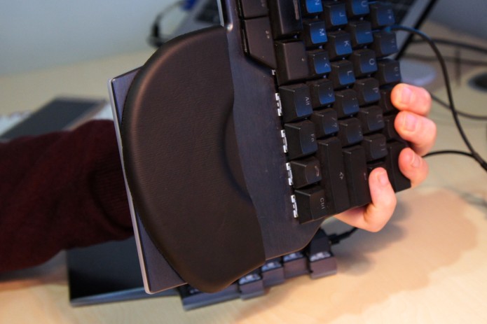
Anti-slip / adhesive layer
This new sample has a thin layer of adhesive material so it will stick to your keyboard. What's also great about it is you can clean it with water and it will still stick!
THE FINAL SOLUTION
We are happy to be using this new sample for our palm pads. It will have our palm pad shape and have the curved edges that we want.
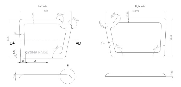
Dimensions of the palm pads
We like the new solution for the anti-slipping. We also like and prefer the softness.
Our new manufacturer told us that we can also create thicker or thinner palm pads with the same material in the future.
It will still be a challenge to manufacture but we have already decided to pay the tooling. We will do a short batch and test it properly.
What do you guys think?
Apart from these development updates, we also have a short tech video from Matt where he shows us the cause and effect of switch bouncing.
Switch bounce and debounce delay
Switch bounce, switch delay, and switch debouncing
When a mechanical switch is pressed, it doesn’t just make an on-off contact - it actually creates a series of short contacts, before becoming either on or off. This is called ‘switch bounce’ because the contacts are literally bouncing on each other before settling.
This is something we have to take care of in the Raise keyboard.
A switch bounce can be seen using an electronics tool called an oscilloscope. Each bounce could be as short as a millionth of a second, and the time it takes a switch to stop bouncing is about 1 thousandth of a second.
Switch manufacturers usually guarantee bounce time to be less than 5 thousandths of a second.
It sounds like a very short amount of time but because the microcontrollers are scanning the switches at a similar speed, there can be a problem where for one key press, there might be six or seven contacts recorded. If we slow down the speed of the scanning, we get fewer bounces - but we also increase the latency of the keyboard.
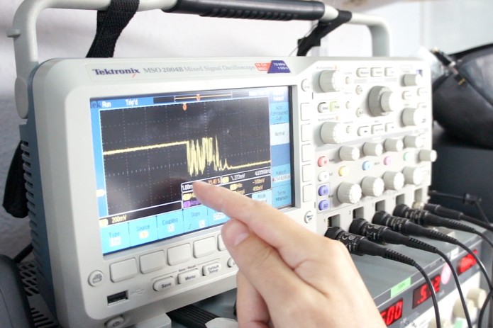
Checking the switch bounce of a Clicky switch
We have to filter these bounces out somehow. At the moment, we read each switch repeatedly, and only when it has stayed on for a period of time do we send the signal to the computer. This period is called the debounce delay - it’s the time that you’re filtering out all those signals that you don’t want to send to the computer. With mechanical switches, you will always have this delay time.
____________
We hope you guys liked our somewhat educational update! We'd greatly appreciate your feedback. Tell us what you like, what you don't like, and what we can do to make things better :)
Thanks!
- Dygma Team
____________
Like us on Facebook
Follow us on Twitter
Follow us on Instagram
Subscribe to our Youtube
Fri Oct 26 '18 Announcement
over 7 years ago
– Fri, Oct 26, 2018 at 02:34:42 PM
Hey guys!
Here are the updates on the latest developments from our recent trip to China.
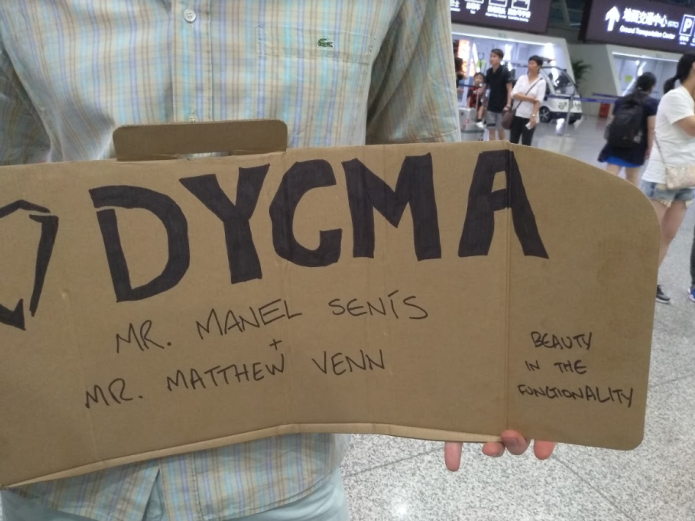
One of our Superbackers met Manel and Matt at the airport in China
This last trip to China was our fourth. The first trip was in July 2017, the second and third were in January and May of this year.
Prior to our most recent trip, we already validated our industrial design. We made the necessary iterations and found the solutions we needed.
But when it came to the manufacturing process, there were some doubts. We were worried about quality control and timing. So during this trip, we made sure that we discussed all of these doubts with our partners. Thankfully, all things were clarified and we left China on a positive note.
Our first goal for this trip was to finalize everything related to the product design. This included the electronics and the quality of the metal finishing. Our second goal was to learn about the manufacturing process so we could create a planning schedule.
The good news is now we know more about manufacturing processes. We have a clearer vision of the future. The bad news, it will take longer than expected. Our manufacturers told us that the tooling for certain components would take as long as 45 days to create.
We have prepared a Gantt chart at the end of this update. But before we talk about that, we want to update you on what we’ve been working on at hand.
Silver Golden Prototype
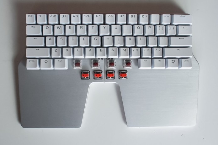
We received the silver Raise Golden Prototype. This version has the ANSI layout.
Silver Raise with US PBT keycaps
We still don't have the white special keycaps. The reason is that, as we mentioned in previous updates, these special keycaps will be made using a mold. That mold still needs to be created. In the photo above, we used the 3D-printed black special keycaps.
We also validated the white ABS keycaps.
Silver Raise with ABS keycaps
We were also happy with the finishing and dimensions of the metal pins.
As some of you might remember, the metal pin solution for the joint was something that we were working on for a long time. We wanted it to have the right feeling when detaching and attaching both sides. Once attached, we also needed enough magnetic force to keep the keyboard intact.
We also validated the finishing of the metal cover of the Huble.
Silver and black cover
Another metal component that we validated was the silver top case. Both silver and black top cases look awesome.
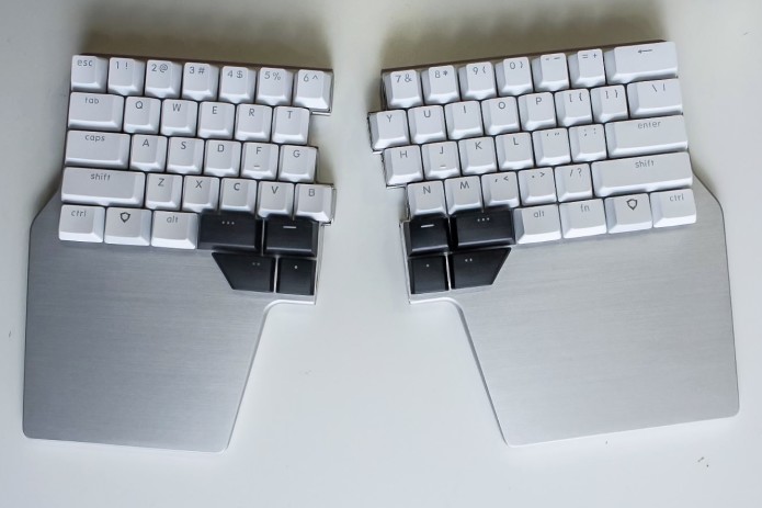
Silver Raise
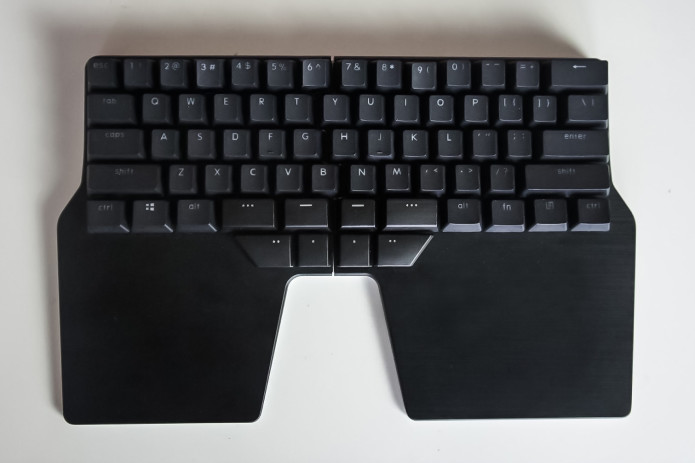
Black Raise
Electronics
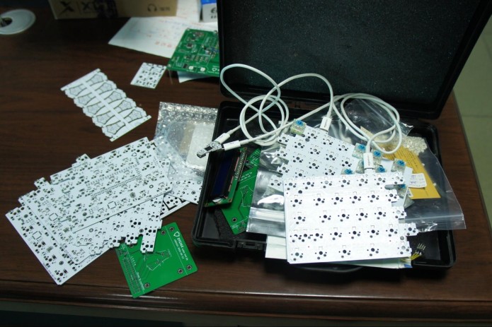
PCBs of the Raise
When in China, we visited our PCBA factory. We gave them our Huble test jig to reproduce. We asked them to make as many test jigs as they can.
There should be a test jig for each PCB, and we have 5! As you might remember from Matt’s video, the Huble has one PCB and Raise has 4 PCBs, -2 main PCBs and 2 low profile PCBs.
We are now working on the other test jigs. Once they’ve been tested and finalised, we'll send them to China. Our partners will then reproduce them to use for mass production.
We also did the pre-test for our PCBs. By doing these pre-tests, we can be certain that our product will pass the real certification after mass production.
There were 3 tests. We passed 2 and failed 1. We are working with a consultant to fix the issue. We will make a video and explain all of this in our next update.
Packaging
The packaging was something that we left till the end because we wanted the product to be properly defined first. Now we have the final dimensions of the package, the color, and the artwork.
The product will be enclosed in a PET plastic case for protection. The extra switches and keycaps will be in a separate case. There will be a foam on top of the cases to keep them all in place.
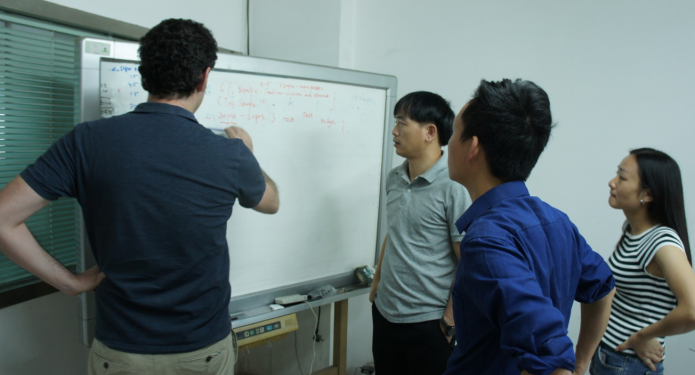
Meeting with partners
Tooling Agreement
We already defined all legal agreements with our suppliers. This included the Manufacturing Agreement, Tooling Agreement, Purchase Orders, Quality Control Agreement, etc. They needed to be translated and discussed with all our partners. It was a long and difficult process but it was also important.
Manufacturing Process
There are different phases to the manufacturing process. First is the EVT or engineering validation test. We already did this when we validated our industrial design.
Next is making the tooling. We need 15 different tooling for the Raise. While some of the tooling can be made in a week, some need 45 days.
After all the tooling have been created, we will test them (T1, T2, T3). This might take a week. If we find mistakes in T1, we'll modify things and do T2. T3 is for emergencies. Hopefully, it doesn’t get here and we can fix everything by T2.
Toff is a milestone. This is when we validate all tooling pieces as perfect and ready.
Next is the DVT or Design Validation Test. This will take 30 days. In this test, we will create 20-50 units and validate them. If all is well, we will proceed to mass production.
If not, we would need to do the PVT or Production Validation Test. This will take another 30 days. We will only do this test if we still see problems after the DVT. We hope that we won't need to go through with this anymore.
We also have to take into account the Chinese New Year. This will be a 3-week holiday for most people in China. We have to put allowance during this time.
After the DVT or PVT, we will start mass production of the remaining units. This might take as long as 40 days; but optimistically speaking, it can take 30 days.
Then shipment!
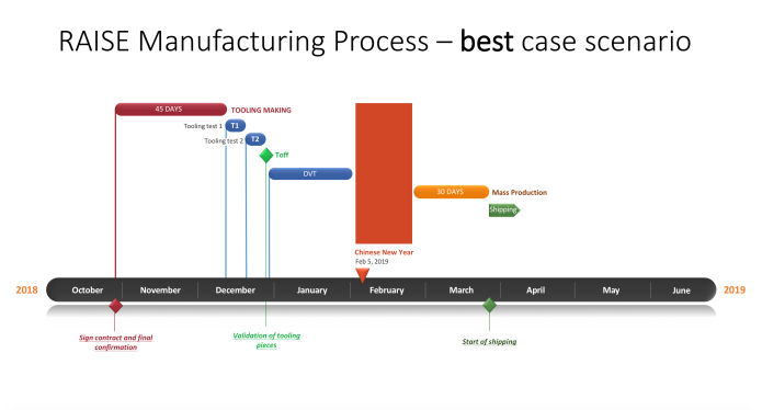
The Gantt charts below show 2 scenarios: the best and the worst case
Best scenario:
- We won’t need a long time for tooling testing
- We won’t do T3
- We won’t do the PVT
- Mass production will take 30 days
- Shipment will be at the end of March to mid-April
Click here to open the chart.
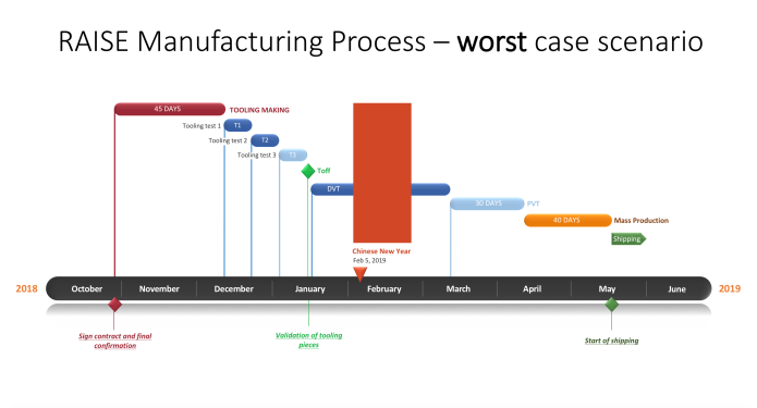
Worst case scenario:
- Tooling testing will take longer
- We will need to do T3
- We will need to do the PVT
- Mass production will take 40 days
- Shipment will be mid-May
Click here to open the chart.
The Raise is a complex product. There are hundreds of variants because of the different switches, keycaps, and color that we offer. But our suppliers are optimistic. They think it won’t be hard to assemble.
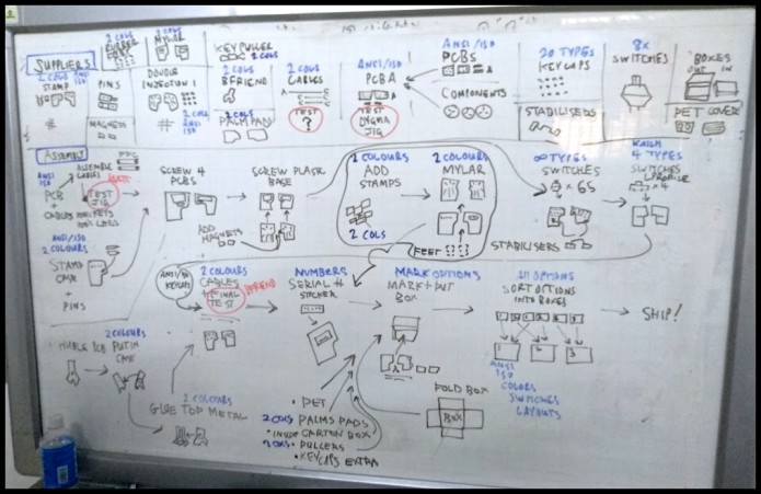
Assembly of the Raise
When we learned about the timeline and how long it would take, we all felt a bit disheartened. But at the same time, we felt relieved that now we have a clearer vision of the manufacturing process. We will try our best to work as fast as we can. But we won’t rush the process if it will risk the quality of the final product. We've always said that we wanted to give you a high-quality product, and that's what we intend to do.
We will completely understand that some of you won't be able to wait that long. We will compensate in any way possible without a problem.
Everything that we’ve been through has been a great learning process. And we wouldn’t have been able to go through this if it weren’t for all of you, our backers. So thank you all for being with us and supporting us all this time.
You guys rock!
- Dygma Team
____________
Like us on Facebook
Follow us on Twitter
Follow us on Instagram
Subscribe to our Youtube
Fri Oct 19 '18 Announcement
over 7 years ago
– Fri, Oct 19, 2018 at 09:32:24 AM
Hey there guys! ?
Manel and Matt arrived last Friday from China. They had a productive and busy trip, and have still been busy since then. We have tons of content that we need to sort out. We will post a thorough update about their trip and all the developments soon! So stay tuned!
For now, we prepared a more informational and ‘fun’ piece of content for all of you to learn from and enjoy.
· Matt talks about the 4 PCBs of the Raise
· Matt and Dominique talk about different kinds of switches and mechanical switches
An explanation of the PCBs of the Raise
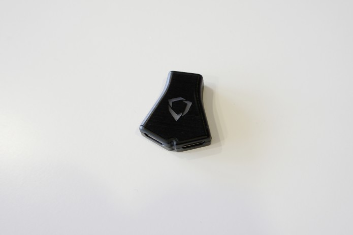
Huble - the brains of the keyboard
The Huble is a separate piece that you connect to your computer and to the 2 sides of the keyboard. It is the brain of the keyboard; the microprocessor and memory is inside it. The cables that come with it are all detachable.
The reason that we created this separate piece is because we want you to be able to use either the left or right side on its own. This means we can't have the USB chip in one side or the other. We would need either two separate USB keyboards or have the USB chip split and then split the wires down into the keyboards.
The electronics in the Huble deals with the USB and talking to the PC. The electronics in each of the keyboards deals with reading the key presses and controlling the LEDs.
Inside the Huble, we have a circuit board that has a USB-C socket to get the USB data. This has the power to control the whole keyboard.
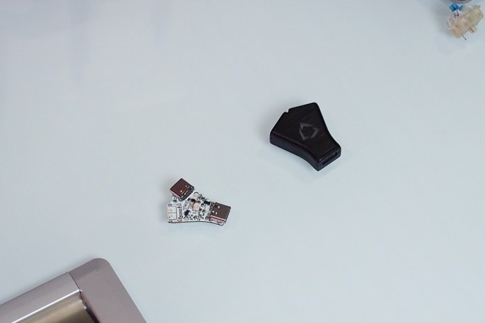
The microprocessor on the back is what does all the work. We load the firmware onto that and that does all the coordination. It talks to the computer via USB and it talks to the keyboard sides with a protocol called I2C.
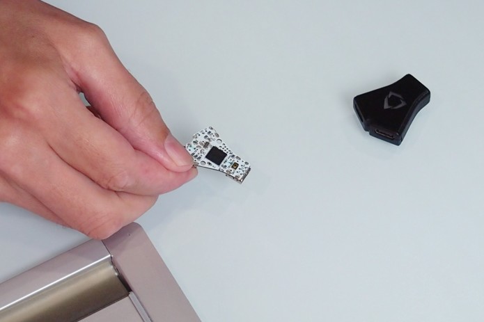
All the information comes out of these two sockets.
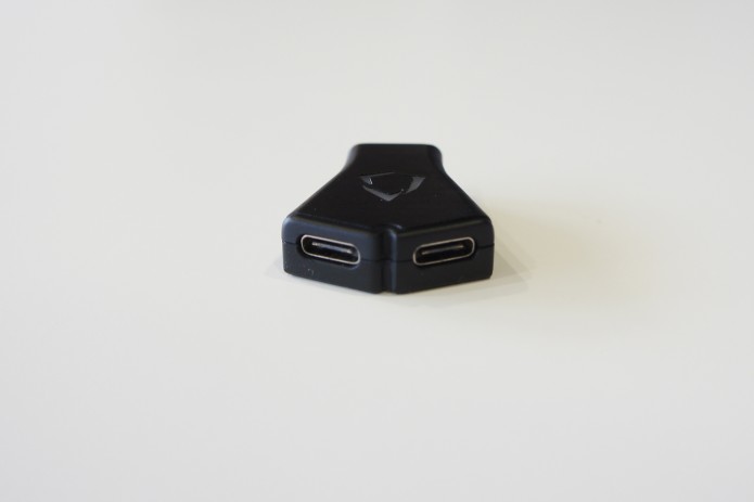
We've also got an LED on the front to shine out of the Dygma logo.
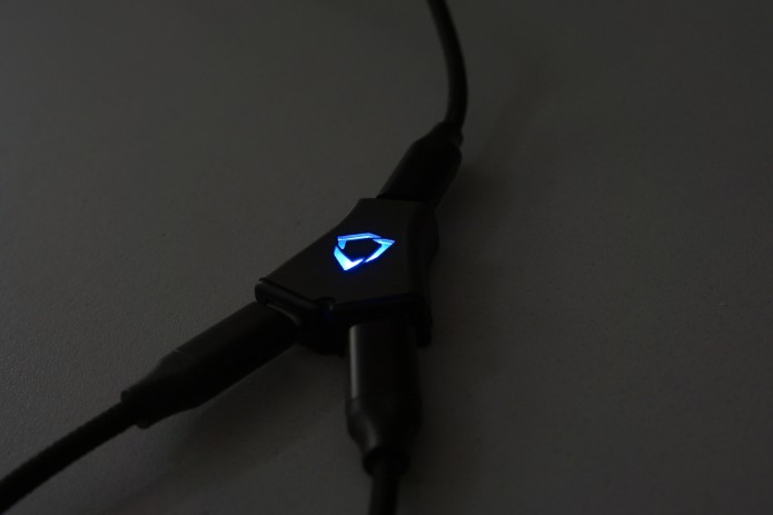
We have a reset button at the back of the Huble, in case stuff goes wrong or to help with uploading new firmware.
What happens after the data and the power come out of the Huble?
The data comes down through 2 USB-C cables and into the USB-C sockets on the back of the keyboards.
Inside the two keyboards, we have 4 circuit boards. The 2 main PCBs and the 2 low profile PCBs.
The power and the I2C communication comes down the cables in to the PCBs. We have a little soft start circuit so that if you plug it all into the computer together, we don't get a big power supply jolt.
The main computer on each side is the microchip, which is an 8-bit microcontroller from Atmel. Its job is to read all the keys as quickly as it can and to control the LEDs.
So if the keys are going to all be red, the Huble sends the information down the I2C, then the microcontroller receives that information. They then send the data to tell the LEDs to go red to the LED driver, which is the chip that controls the LEDs.
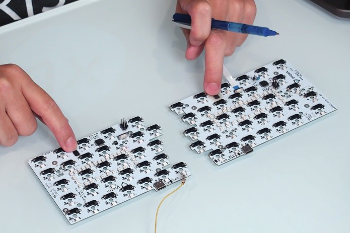
How do the keys connect to the keyboard?
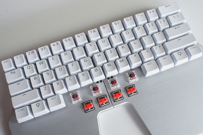
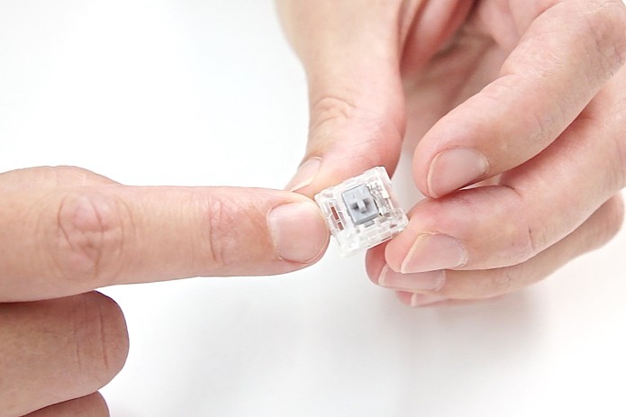
For every key, we have a corresponding socket. They are the hot plug sockets that let you change your switches so you can pull them in and out.
Once the key is latched into the top plate, you would need a switch puller to help you unclip it.
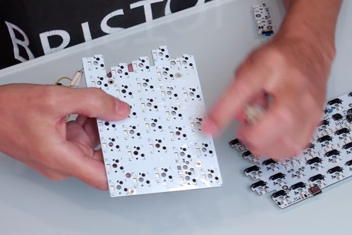
Underneath, we have reverse mounted RGB LEDs, as well as a diode for each key. The diode has to do with scanning the matrix of keys together because instead of reading each key individually, we're scanning them in a kind of column and row matrix.
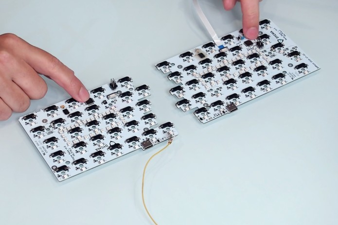
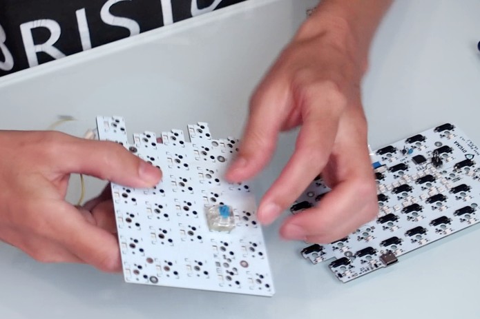
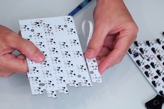
How are the main PCBs connected to the low profile PCBs?
One important part of the PCB is this little plug where we connect the circuit boards of the low profile switches.
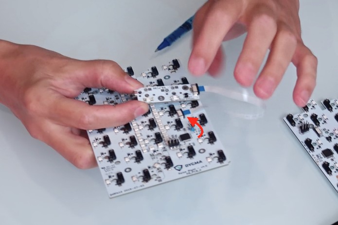
The smaller circuit boards have their own two LEDs and their own set of sockets for the low profile switches.
The low profile switches are thinner. So we had to have the low profile PCB at a different level; it had to be a little bit higher than the normal PCB so that it could fit properly. That is why we had to have a separate PCB.
They are connected with a flexible wire and clipped together with a plug.
Next up, switches!
Switches and mechanical switches
Dominique visits Matt’s workshop and picks Matt’s brain.
They talk about switches, how they work, and the types of mechanical switches.
A switch is a device that either allows or stops the flow of electricity. Normally, electricity is trying to get from one point to another. If you had a wire, electricity will continue to flow. But if you break the wire, then the electricity won't flow; and a switch is a piece that allows you to join the wires together.
What are some of the switches that Matt has lying around his workshop?
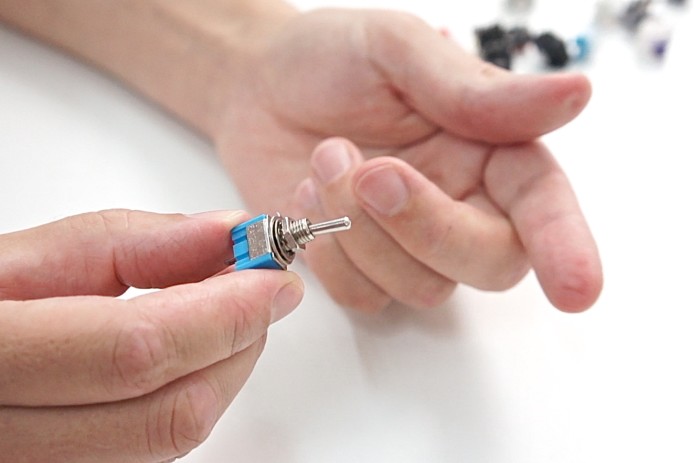
Toggle switch. This switch is mainly used to turn something on or off.
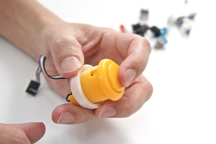
Push-button. A simple switch used commonly in arcade games.
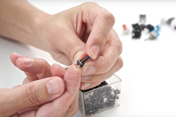
PCB mounted tactile switch. These are the switches you would normally mount on a PCB.
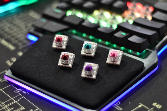
Mechanical switches. These switches have been designed with specifications suitable for typing.
How does electricity flow through a mechanical switch?
Electricity flows through the crosspoint contact. When you press a key, the two metal components get in contact with each other, thus registers a key press.
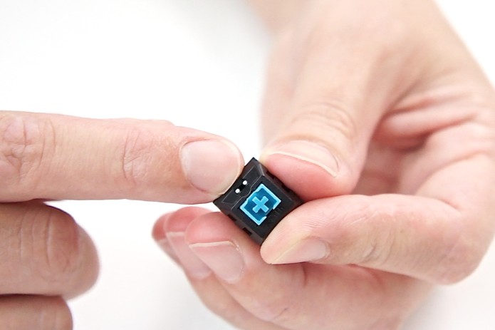
Why do some mechanical switches have a white/transparent bottom and some have a black bottom?
Manufactures have created different solutions to allow light to come out through switches.
For example, this transparent mechanical switch has got a cut in the side of the shell so that you can put an LED underneath it and light will shine up through the top.
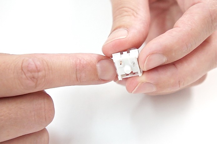
If it's got a solid black base, then you'd have to put the LED on the top.
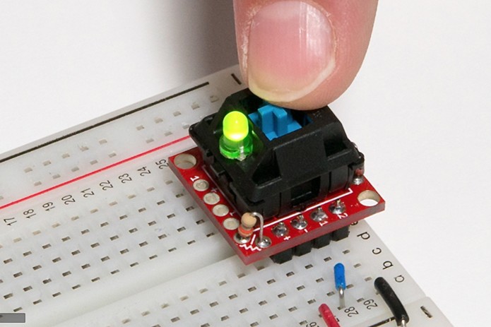
The little round hole there is where you put the LED.
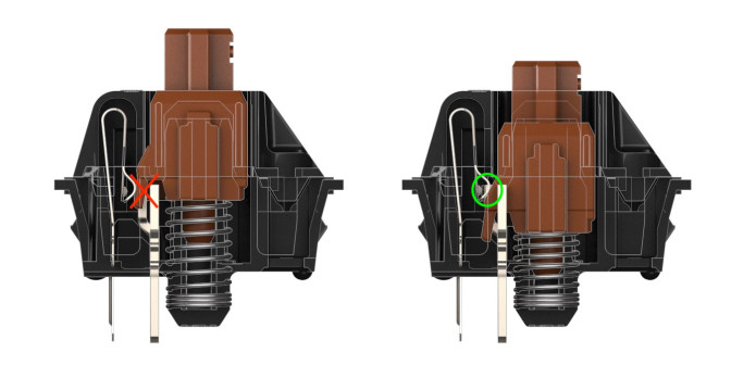
What are the types of mechanical switches that can fit with the Raise?
All mechanical switches that have this center pin and then have the two pins offset can fit in the Raise.
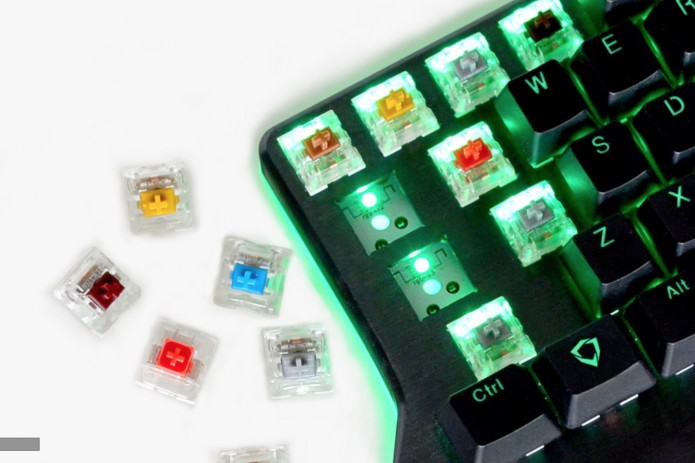
What are the three types of switches?
These three basically come down to the feel of the switch. Different people love different types of switches and it's a very personal choice.
You also get different springiness, so this will affect the amount of force you need to make the switch press. You could have a very light touch or a heavier touch.
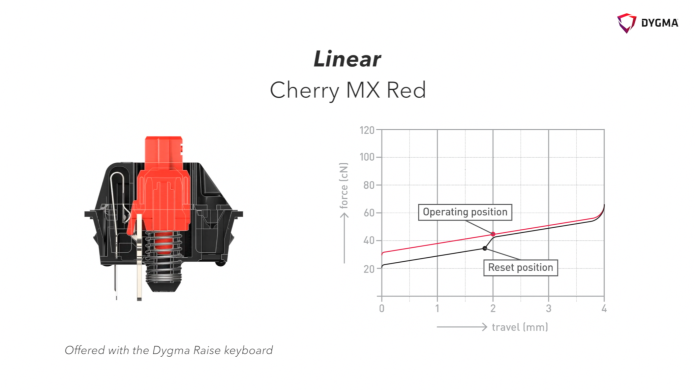
Linear
With a linear switch, it takes a linear amount of force as you actuate and de-actuate it. It has a smooth smooth press all the way down.
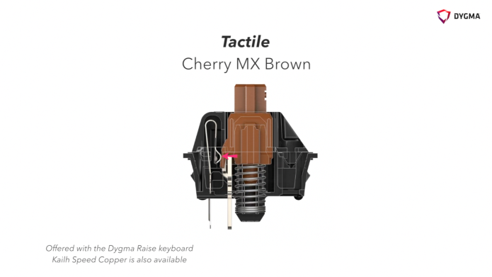
Tactile
With the tactile, as you press it, you feel a bump in during the key press. But if you press it fast, you don't notice it much.
The hump at the wing of the stem causes that little bump.
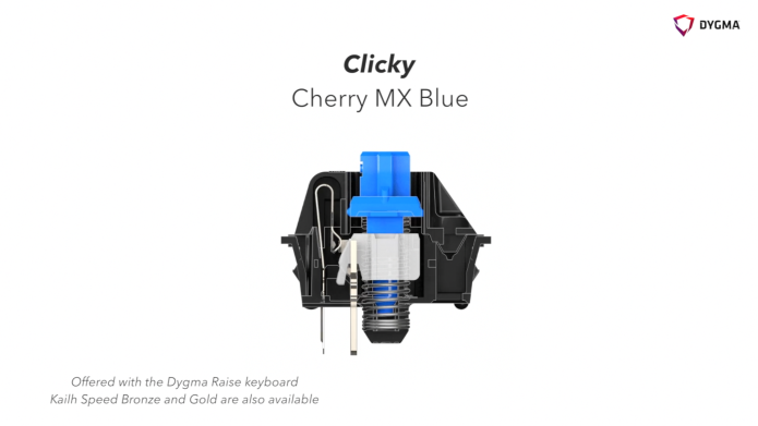
Clicky
There are two pieces of the stem in the clicky switch - the blue piece and the white piece. When actuated, the white plastic piece pops out of the way. As the white bit hits the bottom, that's what makes the sound.
We hope you enjoyed this update! If you have any questions or comments, feel free to write them below!
Again, we will be posting another update soon regarding the developments from China and the schedule of the production process. So stay tuned!
Thanks again guys!
- Dygma Team
____________
Like us on Facebook
Follow us on Twitter
Follow us on Instagram
Subscribe to our Youtube